Welding inspection sits on a foundation of precise vocabulary. A weld face is not a fusion zone. An imperfection is not a defect. A welder qualification is not a welding procedure qualification. Each pair sounds similar to an outsider. To anyone signing off a welded fabrication, the difference is the difference between an accurate report and an ambiguous one.
This bulletin sets out the terms an inspector working to BS EN ISO 17637 needs to use correctly. It does not try to list every term in the standards. It works through the groups of terms that come up most often during preparation, welding, and inspection of fusion welded joints, and it points to the standards that hold the formal definitions.
BS EN ISO 17637, Non-destructive testing of welds, Visual testing of fusion-welded joints, is the international standard against which welding inspectors carry out visual examination. It calls up other standards for terminology, for symbols on drawings, and for the classification of imperfections. Used together, they give the inspector a single, unambiguous vocabulary.
That vocabulary serves several purposes. It is the language of the welding procedure specification, the procedure qualification record, and the welder qualification certificate. It is the language of the drawing the welder is working to. It is the language of the inspection report when the work is examined. When the same terms mean the same thing across all of those documents, work passes through the chain cleanly. When they drift, errors creep in.
Six published standards carry most of the welding terminology used in inspection.
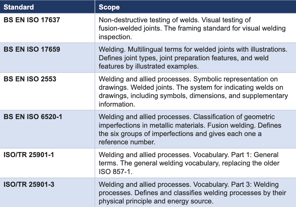
These are the ISO-based standards used widely in the UK and Europe. Two American systems run in parallel and an inspector working internationally needs to recognise both. ASME Boiler and Pressure Vessel Code Section IX governs welding and brazing qualifications in pressure equipment under the ASME system. AWS D1.1, Structural Welding Code, Steel, governs structural steel welding under the American code. The terms in this bulletin sit in the ISO vocabulary. Equivalent ASME and AWS terms exist for almost every concept, sometimes with small differences in scope or definition, and a drawing or specification should always be read against the standard it was written to.
These describe the prepared joint before any weld metal is deposited. They are dimensioned on the drawing and verified at fit up.
Butt joint, fillet joint, lap joint, T joint, corner joint, edge joint
The six basic joint configurations. The butt joint and the T joint are the two most common in pressure equipment and structural fabrication. A butt joint sits with the two parent members in the same plane. A T joint sits with one member at an angle to the other.
Groove and fillet
A groove weld is made into a prepared groove between the two members. A fillet weld is made along the corner where two members meet without any groove preparation. The two terms describe the weld type, not the joint type. A T joint can be welded with a fillet weld or with a groove weld or with both together.
Bevel angle, groove angle, root face, root opening, depth of preparation
The dimensions of the prepared joint. These are covered in detail, with a worked diagram, in our bulletin on weld joint terminology. The short version: groove angle is the total included angle of the prepared groove; bevel angle is the angle of one prepared face from the vertical; root face is the unbevelled vertical land at the bottom of the preparation; root opening is the gap between the two root faces at fit up.
Weld, weldment, welded joint
A weld is the union produced by the welding process. A weldment is the assembled and welded fabrication. A welded joint is the connection made between members by one or more welds together with the adjacent parent metal affected by the welding heat.
Weld metal and parent metal
Weld metal is the metal that was molten during welding and solidified to form the weld. Parent metal, sometimes called base metal, is the metal being joined. A weld between two different parent metals is a dissimilar metal weld.
Fusion zone and fusion line
The fusion zone is the weld metal as a region of the cross section. The fusion line, also called the fusion boundary, is the interface between the fusion zone and the parent metal. The fusion line marks where melting stopped during welding. It is the inner boundary of the heat affected zone.
Heat affected zone (HAZ)
The region of parent metal next to the weld that did not melt but was heated enough to change its microstructure. The HAZ begins at the fusion line and extends out into the parent metal until the peak temperature reached during welding was too low to have any metallurgical effect. The HAZ is parent metal, not weld metal, but it is altered parent metal.
Run, pass, bead, and layer
A run, or pass, is a single progression of the arc along the joint. The deposit left by one run is a bead. A multipass weld is built up by depositing many runs in sequence. A layer is one tier of weld metal across the joint, which may be made up of one bead or several side by side. The root run is the first run, deposited into the prepared root. Fill runs build the bulk of the weld. The capping run completes the weld face.
Weld face, weld root, weld toe, weld throat
The weld face is the exposed top surface of a completed weld. The weld root is the area where the weld intersects the back of the joint, in the region of the original root opening. The weld toe is the line where the weld face meets the parent metal surface. Every weld has at least two toes, one on each side of the face. The weld throat is the smallest section through the weld, perpendicular to the weld face.
Throat thickness (a) and leg length (z)
For a fillet weld, two dimensions are routinely specified. The leg length is the distance from the root of the weld out to the toe along the parent surface. The throat thickness is the perpendicular distance from the root to the face of the weld, through the smallest section. For a fillet weld with equal legs, throat thickness is approximately 0.7 times the leg length. The drawing symbol may specify either, prefixed by the letter z (leg) or a (throat). The same fillet welded in two different sizes is two different welds.
Design throat and actual throat
The design throat is the throat thickness specified on the drawing. The actual throat is what was deposited. Where the deposited weld is larger than design, the throat is greater than design and the weld is over-welded. Where it is smaller, the weld is undersized and fails the specification.
Face reinforcement and root reinforcement
On a butt weld, the face reinforcement is the weld metal sitting above the top surface of the parent plates on the face side. The root reinforcement is the equivalent on the root side. Both are normal up to limits set by the acceptance standard. Excess on either is a defect.
Length of weld and effective length
The length of weld is the total length along the joint. The effective length is the part of that length that meets the specified dimensions. Stop and start craters, taper at the ends of a fillet weld, and any portion outside the specified acceptance criteria are excluded from the effective length.
The position of the joint relative to gravity changes the welding process and the appearance of the deposited weld. The standard for welding positions for steels in BS EN ISO 6947 uses two letter codes. The first letter, P, is the position. The number that follows identifies the orientation. Note that pipe positions also use H, J, L codes for fixed pipe orientations.
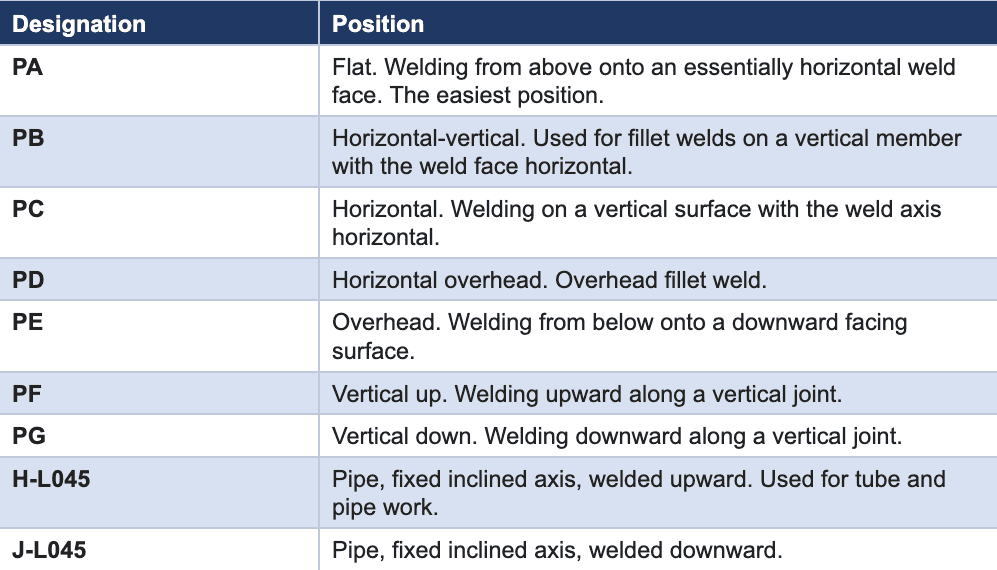
Welder qualifications are position specific. A welder qualified in PA is not automatically qualified for PF or PE. The qualification certificate states the positions the welder has demonstrated competence in, and the welding procedure specification states the positions it covers.
These two terms are not interchangeable, and the difference matters.
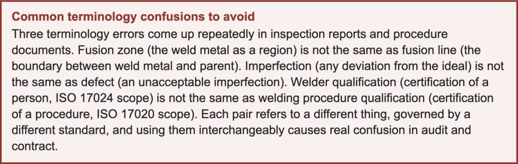
Imperfection is any deviation from the ideal weld. A small amount of porosity, a slight undercut, a small inclusion, all of these are imperfections.
Defect is an imperfection that is judged unacceptable against the applicable criteria. A defect is a failed weld. An imperfection becomes a defect when it exceeds the limits set by the acceptance standard (most commonly BS EN ISO 5817 for steel).
An inspector reports imperfections. The acceptance standard converts those into defects where the limits are exceeded. The two words appear together in BS EN ISO 6520-1, which classifies the geometric imperfections of fusion welds into six groups, each identified by a three-digit reference number.
The six groups under BS EN ISO 6520-1
Welding procedure specification (WPS)
A document setting out the variables for making a weld, including the process, parent metal, filler metal, joint preparation, welding parameters, preheat, interpass temperature, and any required post-weld heat treatment. The WPS is the instruction the welder works to. The format and content depend on the code of construction. Under the ISO system the relevant standards are BS EN ISO 15609 (content of the WPS) and BS EN ISO 15614 (procedure qualification testing). Under the ASME system the equivalent rules sit in ASME Boiler and Pressure Vessel Code Section IX. For structural steel welding to the American system the rules sit in AWS D1.1, Structural Welding Code, Steel.
Welding procedure qualification record (WPQR or PQR)
The record of the test conducted to demonstrate that a welding procedure produces an acceptable joint. The test coupon is welded to the proposed WPS, then subjected to mechanical testing including transverse tensile tests, bend tests, Charpy impact tests, and hardness traverses, plus visual and NDT examination. The qualified WPQR underwrites the WPS.
Welder qualification certificate
A separate document certifying that a named welder has demonstrated the ability to deposit sound weld metal in a defined range of joint configurations, positions, and material groups. Welder qualifications under the ISO system are governed by BS EN ISO 9606-1 for steels and BS EN ISO 9606-2 for aluminium. Under the ASME system, welder qualification sits in ASME Section IX. Under the American structural code, welder qualification sits in AWS D1.1. Welder qualifications are independent of the welding procedure qualification under all three systems. The same WPS may be worked by different qualified welders. The same welder may work to different qualified WPSs.
Welding coordinator
A person with the technical knowledge and responsibility to plan, control, and supervise welding activities. The requirements are defined in BS EN ISO 14731. For higher quality welding to BS EN ISO 3834, a welding coordinator with appropriate qualifications must be appointed.
Visual testing (VT)
The basic NDT method, carried out by the eye assisted by suitable lighting and access. ISO 17637 sets out the requirements for visual testing of welds, including the illuminance level (minimum 350 lux at the surface, with 500 lux recommended), the viewing distance, the angle of view, and the use of aids such as gauges, magnifiers, and mirrors.
Direct and indirect visual testing
Direct visual testing means that the eye is within 600 mm of the surface being examined, with a viewing angle of at least 30 degrees to the surface. Indirect visual testing uses mirrors, endoscopes, fibre optics, or video equipment to view areas where direct access is not possible.
Inspector, examiner, witness, third party
These terms are sometimes used interchangeably but carry different meanings. A welding inspector carries out visual inspection of the work. An examiner is responsible for verifying that test specimens meet the requirements and is named on certificates of qualification. A witness is present during a test or operation to confirm that it was carried out correctly. A third-party inspection is performed by an independent body that is neither the manufacturer nor the customer. NECIT operates as a Type A inspection body under ISO/IEC 17020, which is the highest category of independence for third-party inspection.
Consistent terminology is what makes inspection auditable. NECIT applies the terminology of the standards across all three accredited divisions.
Welding Certification.
Our welding certification scheme operates under two distinct accreditations. ISO/IEC 17024 accreditation covers certification of welders and operators against any applicable international standard, including BS EN ISO 9606 (in its parts for steels, aluminium, and other metals), ASME Section IX, AWS D1.1, and the equivalents used in other sectors. Separately, our ISO/IEC 17020 inspection body accreditation covers the witnessing of welding procedure qualification record test coupons and the associated mechanical testing, against BS EN ISO 15614, ASME Section IX, AWS D1.1, and other international procedure qualification standards. The two accreditations are kept separate because they cover separate activities defined by different standards.
Vendor Inspection.
Our Vendor Inspection division applies the standard terminology in inspection reports, hold point releases, and material certification reviews. The vocabulary in our reports follows the same standards the design and welding documents are written to, which lets clients and auditors trace requirements consistently from drawing through to fabrication record.
NDT and Testing.
Our UKAS accredited NDT division applies the BS EN ISO 6520-1 classification system in characterising and reporting weld imperfections. Personnel are certified to BS EN ISO 9712. Visual inspection is carried out in accordance with BS EN ISO 17637, with the illuminance, viewing distance, and viewing angle requirements applied throughout.
Sindo Kou, Welding Metallurgy, 3rd ed., Wiley, 2020.
ASM International, ASM Handbook, Volume 6A: Welding Fundamentals and Processes, T. Lienert, T. Siewert, S. Babu and V. Acoff (eds.), ASM International, Materials Park, OH, 2011.
Robert W. Messler, Jr., Principles of Welding: Processes, Physics, Chemistry, and Metallurgy, Wiley, 1999.
NECIT: when what’s built must not fail.
